1. Introduction and Purpose of This Manual
This service manual provides detailed technical information and procedures for the maintenance, repair, and overhaul of Ford 555A, 555B, and 655A Tractor Loader Backhoes. It is intended for qualified service personnel and technicians to ensure proper servicing and optimal performance of the equipment. The manual covers various systems and components, offering step-by-step instructions and illustrative diagrams.
This image shows a close-up of the manual's internal title page, displaying 'FORD 555A 555B 655A' and an illustration of a tractor-loader-backhoe. The text 'TRACTOR-LOADER-BACKHOE REPAIR MANUAL' is prominently featured, along with 'FORD TRACTOR OPERATIONS' and 'PRINTED IN U.S.A.'.
2. هن دستور کي استعمال ڪندي
The manual is organized into distinct sections, each addressing a specific system or component of the tractor backhoe. Each section is tabbed for easy navigation, allowing users to quickly locate relevant information. Procedures are presented clearly, often accompanied by diagrams and illustrations to aid understanding. It is recommended to review the entire section pertaining to a specific repair before commencing work.

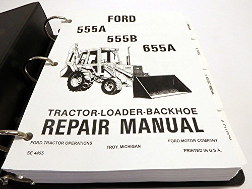
This image displays the open service manual, revealing its ring-bound structure and several tabbed sections. Visible tabs include '1. ENGINE', '2. FUEL', '3. ELECTRICAL', '4. CLUTCH', '7. REAR AXLE, BRAKES', '8. HYDRAULICS', and '12. SEPARATING'. This organization facilitates quick access to specific repair topics.
3. عام حفاظت جي ڄاڻ
Always prioritize safety when performing any maintenance or repair procedures. Read and understand all safety warnings and precautions outlined in this manual and on the equipment itself. Use appropriate personal protective equipment (PPE) and ensure the work area is safe and clear of hazards. Disconnect power sources and relieve hydraulic pressure before working on relevant systems. Refer to local safety regulations and guidelines.
4. انجن سسٽم
This section details the various engine systems, including fuel delivery, lubrication, and cooling. It provides instructions for inspection, adjustment, repair, and replacement of components such as fuel injection pumps, filters, lines, and cooling system parts. Proper functioning of these systems is critical for engine performance and longevity.
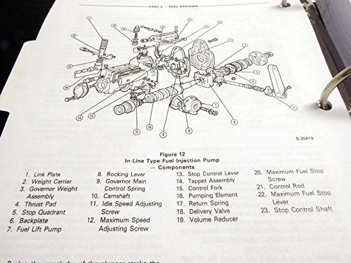
4.1 Fuel System Components
Detailed diagrams illustrate the components of the fuel injection system, aiding in identification and assembly. Each part is numbered and labeled for clarity.
This image displays a technical diagram titled 'Figure 12 In-Line Type Fuel Injection Pump - Components'. It shows an exploded view of the pump with various parts numbered from 1 to 23, including the Link Plate, Rocking Lever, Governor Weight Assembly, Thrust Pad, Stop Quadrant, Fuel Lift Pump, Governor Main Control Spring, Camshaft, Idle Speed Adjusting Screw, Maximum Speed Adjusting Screw, Stop Control Lever, Tappet Assembly, Control Fork, Pumping Element, Return Spring, Volume Reducer, Maximum Fuel Stop Screw, Control Rod, Maximum Fuel Stop Lever, and Stop Control Shaft.
5. بجلي جو نظام
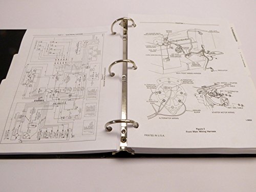
The electrical system section covers wiring diagrams, component testing, and repair procedures for the tractor backhoe's electrical circuits. This includes the starting system, charging system, lighting, and various electrical accessories. Proper diagnosis of electrical issues requires careful adherence to the provided schematics.
This image shows a page from the manual featuring an electrical wiring diagram. The diagram illustrates various electrical connections and components, including the alternator, starter motor, and associated wiring harnesses. The text 'CHAPTER 1 - ELECTRICAL SYSTEM' and 'Figure 1 Front Main Wiring Harness' are visible, indicating the context of the diagram.
6. Power Train
This section addresses the power train components, including the clutch, transmission, and rear axles. It provides instructions for disassembly, inspection, repair, and reassembly of these critical systems. Procedures for removing and installing gears, bearings, and other internal components are detailed.
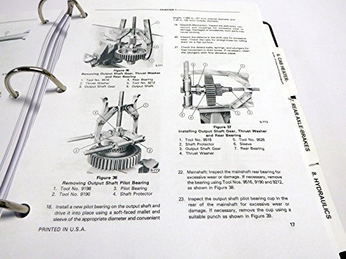
6.1 Output Shaft Gear Service
Instructions for the removal and installation of output shaft gears and associated components are provided, including specific tool numbers for these operations.
This image displays two technical diagrams: 'Figure 36 Removing Output Shaft Gear, Thrust Washer and Rear Bearing' and 'Figure 37 Installing Output Shaft Gear, Thrust Washer and Rear Bearing'. Both diagrams illustrate the process with numbered tools and components, providing visual guidance for these specific power train service procedures.
7. هائيڊولڪ سسٽم
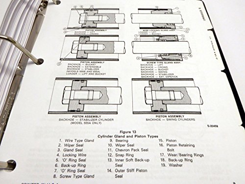
The hydraulic system section covers the various hydraulic circuits, components, and their functions within the tractor backhoe. This includes pumps, valves, cylinders, and associated lines. Detailed information on cylinder gland and piston types is provided to assist in repair and maintenance.
7.1 Cylinder Gland and Piston Types
Understanding the different types of cylinder glands and pistons is essential for correct hydraulic system servicing.
This image presents a diagram titled 'Figure 13 Cylinder Gland and Piston Types'. It illustrates different configurations of piston assemblies for backhoe and loader components, including extendible, crowd, bucket, stabilizer cylinder, and swing cylinders. Various parts such as wire type gland, wiper seal, gland seal, locking wire, O-ring seal, back-up ring, screw type gland, bearing, wiper seal, chevron pack seal, snap ring, inner soft back-up seal, outer stiff piston seal, piston, piston retaining bolt, wear/bearing rings, back-up ring, and washer are numbered and labeled.
8. سار سنڀال جا طريقا
This section outlines routine and periodic maintenance tasks necessary to keep the Ford 555A, 555B, and 655A Tractor Backhoes in optimal working condition. It includes procedures for fluid checks, filter replacements, lubrication points, and component inspections. Specific instructions for tasks like fuel tank removal and oil filter servicing are provided.
8.1 Fuel Tank and Oil Filter Service
Proper servicing of the fuel tank and oil filter is crucial for preventing contamination and ensuring system efficiency.
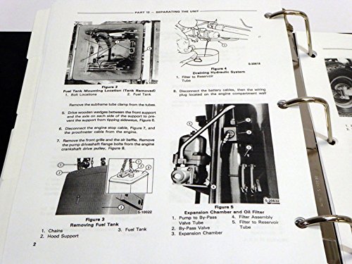
This image displays two diagrams related to maintenance. 'Figure 3 Removing Fuel Tank' illustrates the steps for safely detaching the fuel tank, including using chains and hood support. 'Figure 5 Expansion Chamber and Oil Filter' shows the components of the expansion chamber and oil filter assembly, detailing the pump to bypass valve, bypass valve, expansion chamber, filter assembly, and filter to reservoir tube.
9. مسئلو حل ڪرڻ جي ھدايت
A comprehensive troubleshooting guide is included to assist in diagnosing common operational issues. This section provides symptom-based problem-solving steps, helping technicians identify the root cause of malfunctions and implement appropriate corrective actions. It covers issues across engine, hydraulic, electrical, and power train systems.
10. ٽيڪنيڪل وضاحتون
This manual includes technical specifications pertinent to the Ford 555A, 555B, and 655A Tractor Loader Backhoes. These specifications cover dimensions, capacities, torque values, and other critical data required for accurate service and repair. Refer to these specifications for precise adjustments and component compatibility.
- Manual Form Number: ايس 4455
- صفحن جو تعداد: لڳ ڀڳ 675
- ناشر: TechMedia
- اشاعت جي تاريخ: جنوري 1، 2010
11. Manual Quality and Support
This service manual is a high-quality reprint designed to provide clear and readable content, mirroring the original factory manual. In the event of issues with the manual's physical quality or content clarity, please contact the publisher for assistance. For technical inquiries regarding the content, it is recommended to consult with authorized Ford service centers or experienced technicians.


